Printed circuit board testing is crucial, both for new PCBs and the ones already in use. It enables you to troubleshoot your PCBs, locate issues, and fix them, without needing to replace the whole board or build it again. Nevertheless, it is a complex process. How do you do it? Here’s our guide!
Understanding the Most Common Issues
Before we delve into fixing PCBs, it is essential to understand what to look for. Certain issues occur more frequently. Knowing them will help you solve problems more easily and allocate your time and energy more effectively. So, what issues are most likely to haunt your printed circuit board?
- Component issues - specific, individual components malfunctioning and impacting the overall performance of your PCB.
- Short circuits - usually caused by solder bridging, copper traces touching due to poor insulation, or plating voids.
- Broken connections - caused by physical damage or poor soldering.
- Design issues - problems caused by a faulty design.
Each of these problems requires a different type of inspection. Hence, we recommend starting your printed circuit board testing process by looking for the most common issues. If neither of these occurs, you can inspect more thoroughly to find the culprit.
How to Test a Printed Circuit Board?
Whether it’s during the PCB design process or for troubleshooting, you can apply different methods to test your printed circuit board. What are they? How to test your PCB effectively? Take a look below.
Visual Inspection
You should always start with a visual inspection—it will allow you to detect component issues and some circuit-related problems. What should a visual inspection look like?
- Component damage indicators - cracked, discolored, or swollen components. Also, look for any signs of heat damage.
- Circuit issue indicators - inspect the pins to ensure that they aren’t bent, broken, corroded, or contaminated.
- Connectors and socket issues - check whether connectors and sockets are soldered steadily and not loose.
You can also expand your visual inspection with technology. This is called automated optical inspection (AOI)—a practice in which cameras and microscopes are used to scan the PCB, followed by specialized software that looks for any, even subtle, anomalies that may indicate damage or issues. However, both traditional visual inspection and AOI do not test for all potential defects—they’re a good starting point, which you need to follow up.
In-Circuit Test
In-circuit testing is perhaps the most common method to troubleshoot printed circuit boards. It utilizes an in-circuit tester, a fixture that connects it to the PCB, and specialized software. This method enables you to test out components separately, without them being impacted by other components = you can locate faulty components if that’s the issue.
On the other hand, in-circuit testing can get costly, especially if we factor in the cost of equipment. Therefore, it is best to perform it on stable PCBs, rather than prototypes.
Continuity Testing
You can also test the signal paths and traces in your printed circuit board. For that, use a multimeter or a dedicated continuity tester. This will help you locate any signal continuity issues - then, all you have to do is determine what exactly causes them and whether the problem can be fixed easily.
The Takeaway
The above are just a few of the ways you can test your printed circuit board. In practice, different types of tests are applied when you design and manufacture a PCB, and different ones when you troubleshoot an existing one. Some testing methods worth mentioning include:
- solderability testing,
- peel testing,
- burn-in testing,
- stress testing,
- X-ray testing,
- and boundary scan testing.
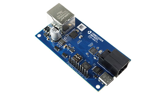
Need help testing your PCB design? Contact us at Conclusive Engineering - we’ll be happy to help!